4 Bit Ripple Counter Using D Flip Flop
The logical circuit of the T flip flop by using the D flip flop is given below. Verilog code for Arithmetic Logic Unit ALU.

Q 6 17 Design A Four Bit Binary Synchronous Counter With D Flip Flops Complete Design Steps Youtube
Verilog code for counter with testbench 21.
. The T flip flop is formed using the D flip flop. Therefore we can see that the output from the D-type flip-flop is at half the frequency of the input in other words it counts in 2s. Circuit which will divide the input clock frequency by 2 4 or 8 times in fact any value to the power-of-2 we want making a binary.
A basic counter circuit is shown in Figure 1 using two triggered T-type flip flop stages. Verilog code for counters with testbench will be presented including up counter down. The top design block consists of four T-Flip Flop.
Ripple Counters 10 41 BCD Ripple Counter Mod-10 A decimal counter follows a pattern of 10 states. Each clock pulse applied to the T-input causes the stage to toggle. For time being ignore the input and output of T-Flip Flop.
The counter produces the output 1100 when the 2 nd clock pulse is passed to the flip flops. In D flip flop the output after performing the XOR operation of the T input with the output QPREV is passed as the D input. Use K-map to derive the flip flop input functions.
A 3-bit counter consists of 3 flip-flops and has 2 3 8 states from 000 to 111. Each JK flip-flop output provides binary digit and the binary out is fed into the next subsequent flip-flop as a clock input. The counter produces the output 1110 when the 3 rd clock pulse is passed to the flip.
The simplest construction of. Design 3-bit synchronous up counter using JK flip flops. We may use some sort of.
Draw the excitation table of the selected flip flop and determine the excitation table for the counter. The circuit of the 3. How to load a text file into FPGA using Verilog HDL 15.
In a ripple counter the flip-flop output transition serves as a source for triggering other flip-flops. Synchronous up Counter counts the number of clock pulses at its input from minimum to maximum. Verilog code for Alarm Clock on FPGA 17.
Verilog code for comparator design 18. Therefore Flip flop 3 output is toggle when there is clock falling edge and Q21 and Q1 1 as you can see from timing diagram. In the final output 1001 which is 9 in decimal the output D which is Most Significant bit and the Output A.
A 4-bit binary ripple counter mod-16 is as follows. Johnson Counter Decade Counter. A Verilog code for a 4-bit Ripple-Carry Adder is provided in this project.
D Flip-Flop is a fundamental component in digital logic circuits. Find the number of flip flops. One flip-flop and latch store 1 bit binary digit of data.
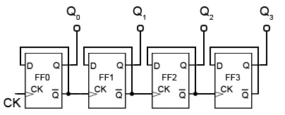
Let us consider the overall outside structure of Ripple Counter. Similarly Flip flop 3 toggle inputT is connected to Q2 and Q1. The Asynchronous counter count upwards on each clock pulse starting from 0000 BCD 0 to 1001 BCD 9.
JK Flip-Flop D Flip-Flop T Flip-Flop D Latch Counters 4-bit counter Ripple Counter Straight Ring Counter Johnson Counter Mod-N Counter Gray Counter Misc n-bit Shift Register Priority Encoder 4x1 multiplexer Full adder Single Port RAM. The counter produces the output 0000 when there is no clock input passed0. To proceed with Verilog Code we shall first understand the structure of the 4-bit Ripple Counter.
Verilog code for D Flip Flop 19. The counter produces the output 1000 when the 1 st clock pulse is passed to the flip flops. Therefore Flip Flop 2 output state Q 2 is toggle only when there is clock falling edge ie -ve edge triggering and Q 1 1.
Verilog Arrays and Memories. By cascading together more D-type or Toggle Flip-Flops we can produce a divide-by-2 divide-by-4 divide-by-8 etc. Verilog code for Full Adder 20.
A binary ripple counter is generally using bistable multivibrator circuits so that cache input applied to the counter causes the count to advance or decrease. We have two inputs ie clock and reset and q is output. Verilog code for 16-bit RISC Processor 22.
The 4-bit ripple-carry adder is built using 4 1-bit full adde. 3-bit synchronous up counter. Verilog code for Traffic Light Controller 16.
Circuit Operation of a 4-bit MOD-16 synchronous counter. The main difference between latches and flip-flop is that a latch changes the output whenever there is a change in input as they continuously checks the input signals and changes in it while flip-flop is a combination of latch and clock which changes the output time adjusted by clock. For a 4-bit MOD-16 synchronous counter circuit to count properly on a given NGT negative transition of the clock only those FFs that are supposed to toggle on that NGT should have J K 1.
The above table state that. The logic diagram of a BCD counter using JK flip-flops is shown below.

Vhdl Code For 4 Bit Ring Counter And Johnson Counter Counter Johnson Rings
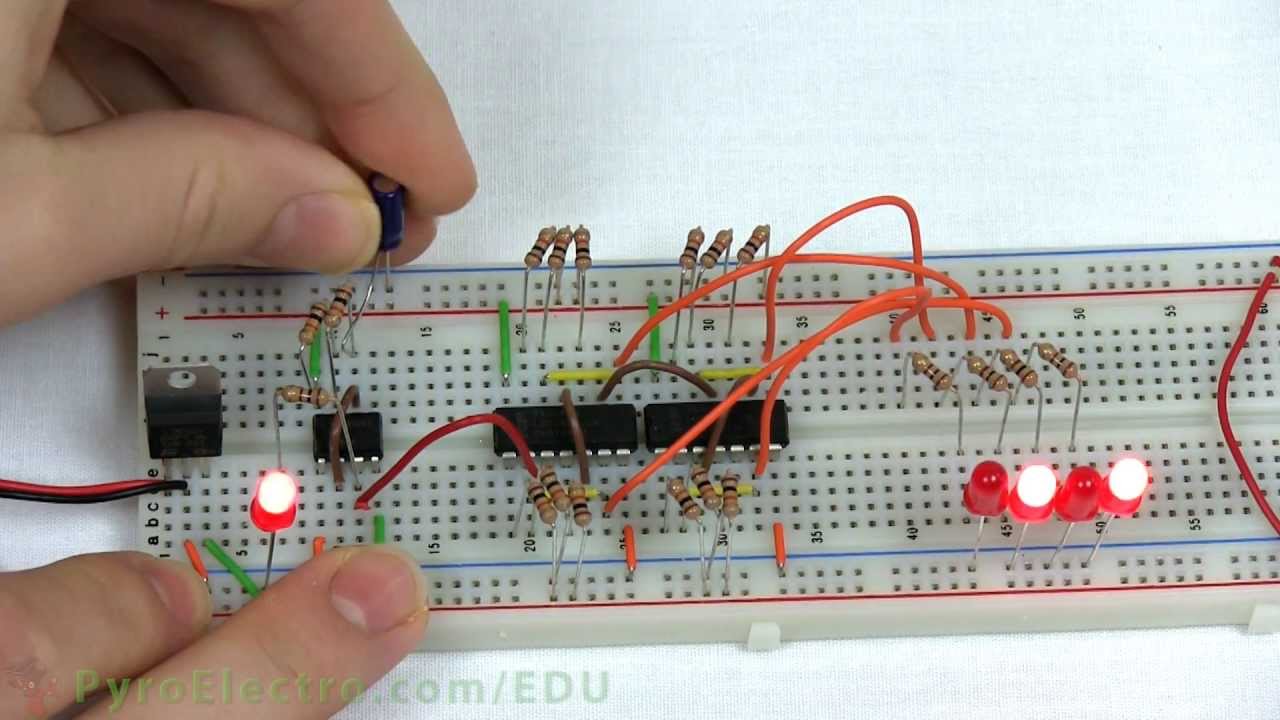
4 Bit Counter An Introduction To Digital Electronics Pyroedu Youtube

4 Bit Asynchronous Ripple Up Counter Using Proteus James Cleves Youtube Binary Code Cleves Coding
Asynchronous Counter
0 Response to "4 Bit Ripple Counter Using D Flip Flop"
Post a Comment